.png&w=640&q=75)

Control Valves
High-precision control valves for automated fluid regulation.
Control Valves Range
Explore our comprehensive range of high-performance control valves designed for critical industrial applications. Engineered for precision, durability, and maximum efficiency.
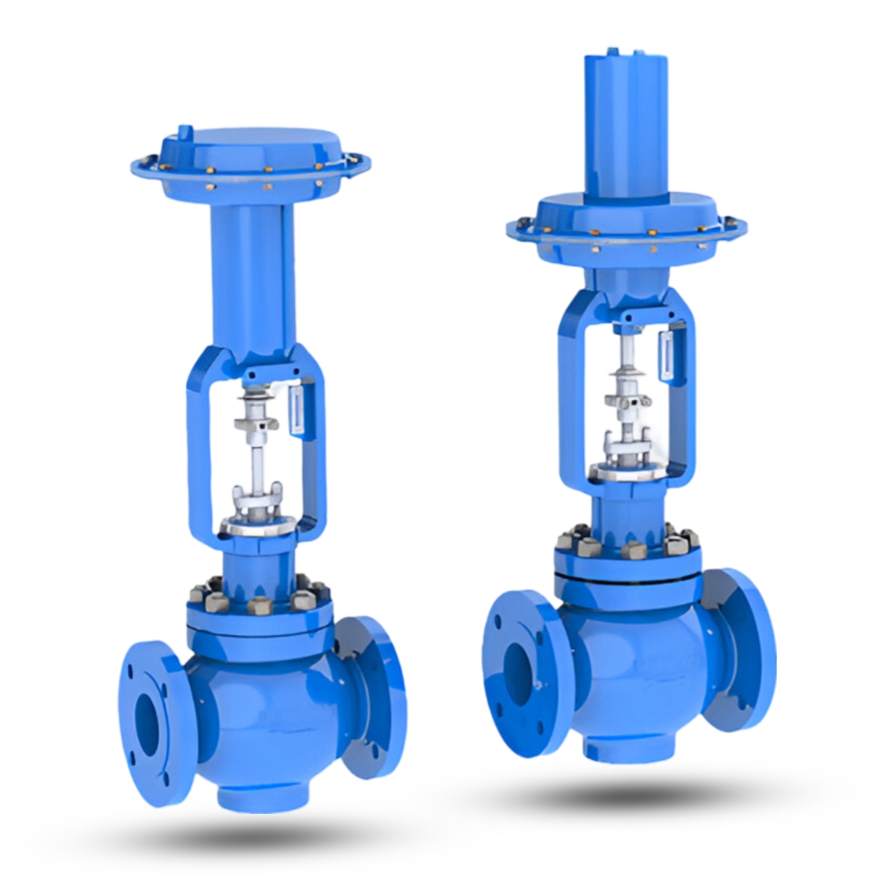
Globe 2 Way Control Valve
This type of Valve with its classic globe body shape, which reflects its name, uses the variable area generated between the plug and seat to control fluid flow. It is very versatile offering reduced trim options as well as a variety of special trims for severe high pressure drop applications. This style of valve is easily adapted for use on cryogenic temperatures and for high temperature duties. This valve is preferred for tight shut-off, positioning accuracy, high rangeability and simplified maintenance, satisfy the majority of control valve applications throughout the process and power industries in control of Air, Steam, Water, Gas, Chemicals etc.
Specifications
Features
- High flow capacity and rangeability.
- Large variety of Trim design.
- Top entry for ease of inspection and maintenance.
- Tight closing for reliable control even when changes in pressure / temperature are sudden and extreme.
- Bolts located outside of the piping stress area to eliminate gasket crush problems.
- Wide selection of actuators to meet most system requirement.
Assurance
- Produced with Quality Systems accredited to ISO 9001 : 2008 by Bureau Veritas and “CE” marked in accordance to Pressure Equipments Directive and Regulations by Lloyd’s Register.
- Full material certification available for all major component Parts.
- Full guarantee on design and Performance.
- All testing performed to the requirements of ASME B16.34.
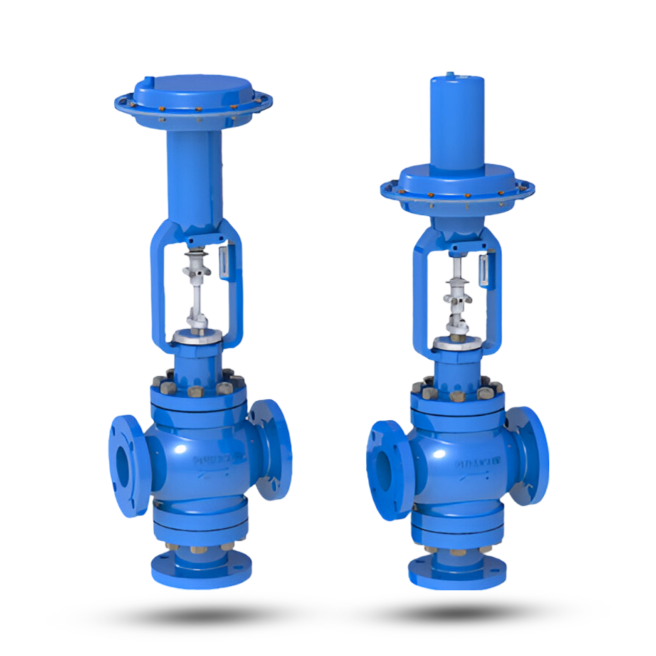
Globe 3 Way Control Valve
This type of Valve with its classic globe body shape, which reflects its name, uses the variable area generated between the plug and seat to control fluid flow. It is very versatile offering reduced trim options as well as a variety of special trims for severe high pressure drop applications. This style of valve is easily adapted for use on cryogenic temperatures and for high temperature duties. This valve is preferred for tight shut-off, positioning accuracy, high rangeability and simplified maintenance, satisfy the majority of control valve applications throughout the process and power industries in control of Air, Steam, Water, Gas, Chemicals etc.
Specifications
Features
- High flow Valve capacity and rangeability.
- Heavy – Duty stem.
- Wide range of interchangeable trim sizes.
- Bellow seals available for positive stem sealing.
- Comprehensively designed and tested to ensure its optimum performance for the tough process parameters specified.
- Wide selection of actuator.
Assurance
- Produced with Quality Systems accredited to ISO 9001 : 2008 by Bureau Veritas and “CE” marked in accordance to Pressure Equipments Directive and Regulations by Lloyd’s Register.
- Full material certification available for all major component Parts.
- Full guarantee on design and Performance.
- All testing performed to the requirements of ASME B16.34.
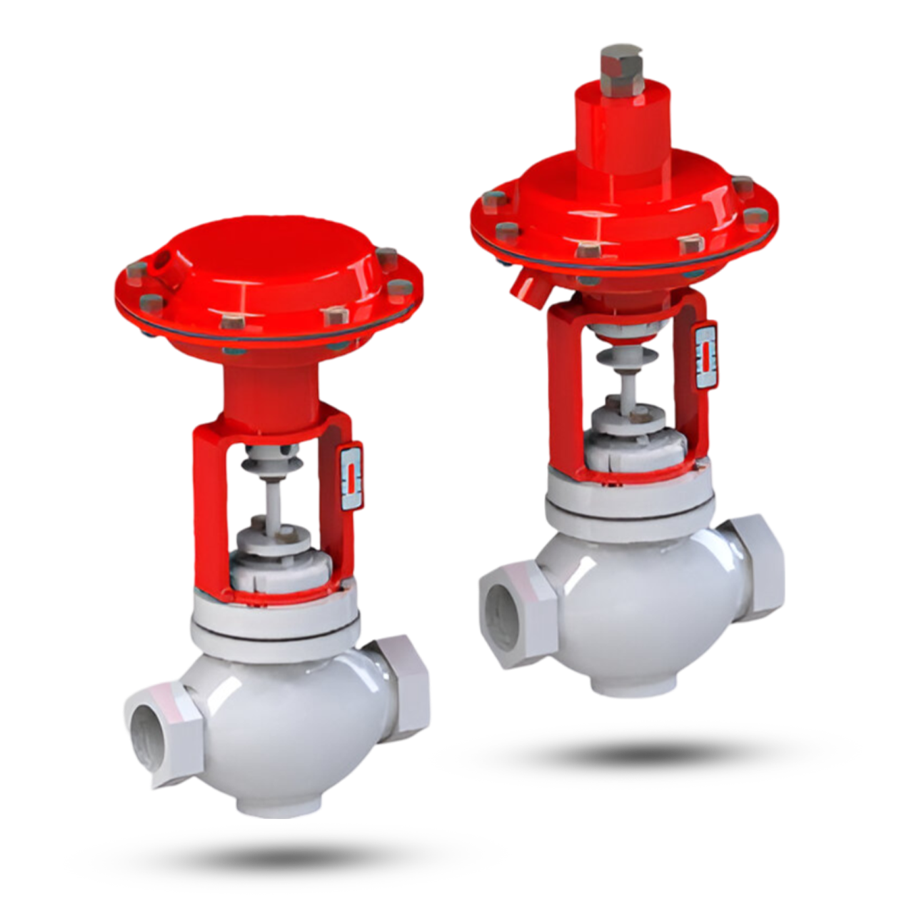
Low Flow Globe 2 Way Valve
This type of Valve with its classic globe body shape, which reflects its name, uses the variable area generated between the plug and seat to control fluid flow. It is very versatile offering reduced trim options as well as a variety of special trims for severe high pressure drop applications. This style of valve is easily adapted for use on cryogenic temperatures and for high temperature duties. This valve is preferred for tight shut – off, positioning accuracy, high rangeability and simplified maintenance, satisfy the majority of control valve applications throughout the process and power industries in control of Air, Steam, Water, Gas, Chemicals etc.
Specifications
Features
- Solid stem connection.
- Suitable for low flow and corrosive atmospheres.
- Available without positioner for fail open or fail close application.
- Corrosion resistance actuator available as an option.
- Investment cast body.
- Wide flow capacity range. Cv ranges from 0.13 to 10.
Assurance
- Produced with Quality Systems accredited to ISO 9001 : 2008 by Bureau Veritas and “CE” marked in accordance to Pressure Equipments
- Full material certification available for all major component Parts.
- Full guarantee on design and Performance.
- All testing performed to the requirements of ASME B16.34.
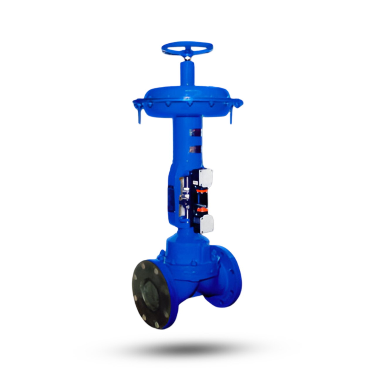
Diaphragm Type Valve
It is a full bore straight through, give high flow performance with minimum turbulence, while giving 100% leak tight closure. Perfect sealing and longer diaphragm life due to weir design. Valve is self cleaning with no pockets, recesses, corners, grooves or sharp edges in the direction of flow.
Specifications
Features
- It is a full bore straight through, give high flow performance with minimum turbulence, while giving 100% leak tight closure.
- Perfect sealing and longer diaphragm life due to weir design.
- Valve is self cleaning with no pockets, recesses, corners, grooves or sharp edges in the direction of flow.
V-Notch Ball Valve
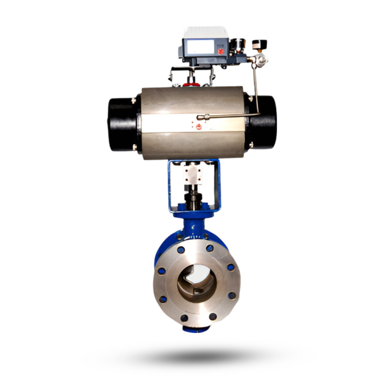
The V-Notch Ball Valve gives non-clogging, high capacity, straight through flow control of fluids containing pulp and paper stock or slurries and fluids containing suspended solids or fibrous materials. V-Notch Ball Valve is quarter turn valve with a segment Ball. The V-Ball create a wedging and shearing effect prevent the dragging of stock or slurry between the ball and its seal The V- Notch Ball Valves are offered squared and clamped driven shaft plus ball shaft with splined connection designed for zero lost motion for highly accurate positioning and precise control.
Specifications
Features
- A Shearing effect between the ball and seal ensures tight shut-off, even on fibrous slurries.
- The unrestricted, straight – through flow design provides high capacity and wide rangeability.
- Precise contouring of the V-notch balls provides a nearly equal percentage characteristic.
- Replaceable ball seal and back up ring for added rigidity.
- Ball machined to a super smooth finish, hard – chrome plated and polished to increase Ball seal life.
- High Cv to body size ratio.
Assurance
- Produced with Quality Systems accredited to ISO 9001 : 2008 by Bureau Veritas.
- Full material certification available for all major component Parts.
- Full guarantee on design and Performance.
- All testing performed to the requirements of ASME B16.34.
Flush Bottom Valve
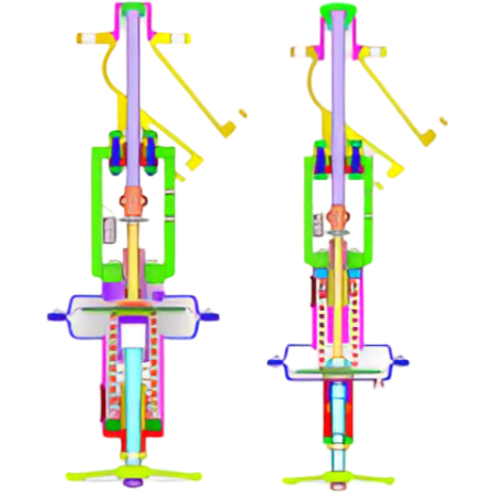
Flush Bottom Valves are used in piping, reactors & vessels to drain out Liquids, Abrasive, Slurry, Viscous Material or Semi Solid Media. Flush Bottom Valves are Available in design of Disc opening into the Tank (Vessel Opening Design) & Disc Lowering (Inside Valve Opening Design) into the Valve Body. Flush Bottom Valves with disc opening into the tank or opening upwards is the most commonly used. It is used where enough space is available between Bottom pad and the stirrer of the tank. The mass load inside the tank helps closing & tight shut off the Flush Bottom Valve. Normally,the inlet size of a standard flush bottom valve is one size higher than that of the outlet size. There are special construction possible with both sizes same. The outlet port is at an angle to the inlet port.Normally 45 or 60 degree deviation is provided. The end connection are normally flanged.
Specifications
Features
- Unique Design Of Flush Bottom Valves assure ” Zero – Hold Up” in the bottom pad of the Tank Facilitate the free flow & quick Discharge of the Liquid or slurry Through the Valve.
- Conical Metal to Metal Disc Seating / PTFE Seating with option of fixed or replaceable seat. Metal Seating can be hard faced by Stellite, where distortion of Seat by aggressive liquid or slurry is common.
- Flush Bottom Valve can also be provided with the temperature sensors to measure the temperature in the vessel.
- Bolted Stuffing Box (Gland), easily adjustable & with Repaceable Service.
Upstream Pressure Regulating Valve
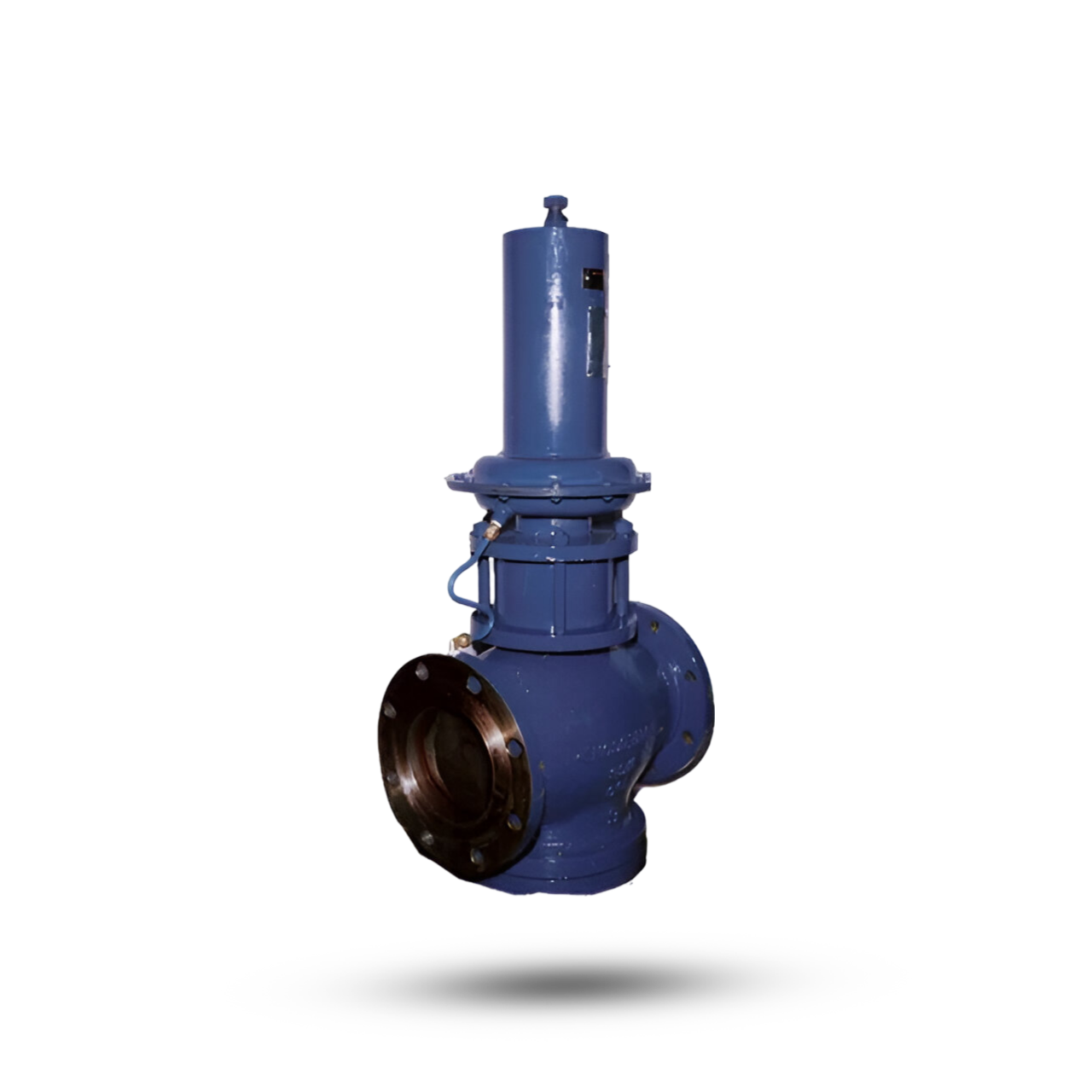
INSTALLATION AND MAINTENANCE AND OPERATING MANUAL FOR SELF ACTUATING PRESSURE REGULATING VALVE (SERIES – 725) GENERAL : This manual describes the instructions for handling, storage,installation, maintenance, and operation of the For self actuating PRV with spring opposed pneumatic diaphragm actuator. Instructions not detailed in this document shall be performed in accordance with standard and safe acceptable practices as may be required by local codes, specifications and or regulations. The instruction contained within this manual must be read before undertaking any work on the equipment supplied and if there are any questions please contact Pneucon Valves Pvt. Ltd. or its agent. When ordering any spares please specify the unique valve serial number detailed on the equipment nameplate.
Downstream Pressure Regulating Valve
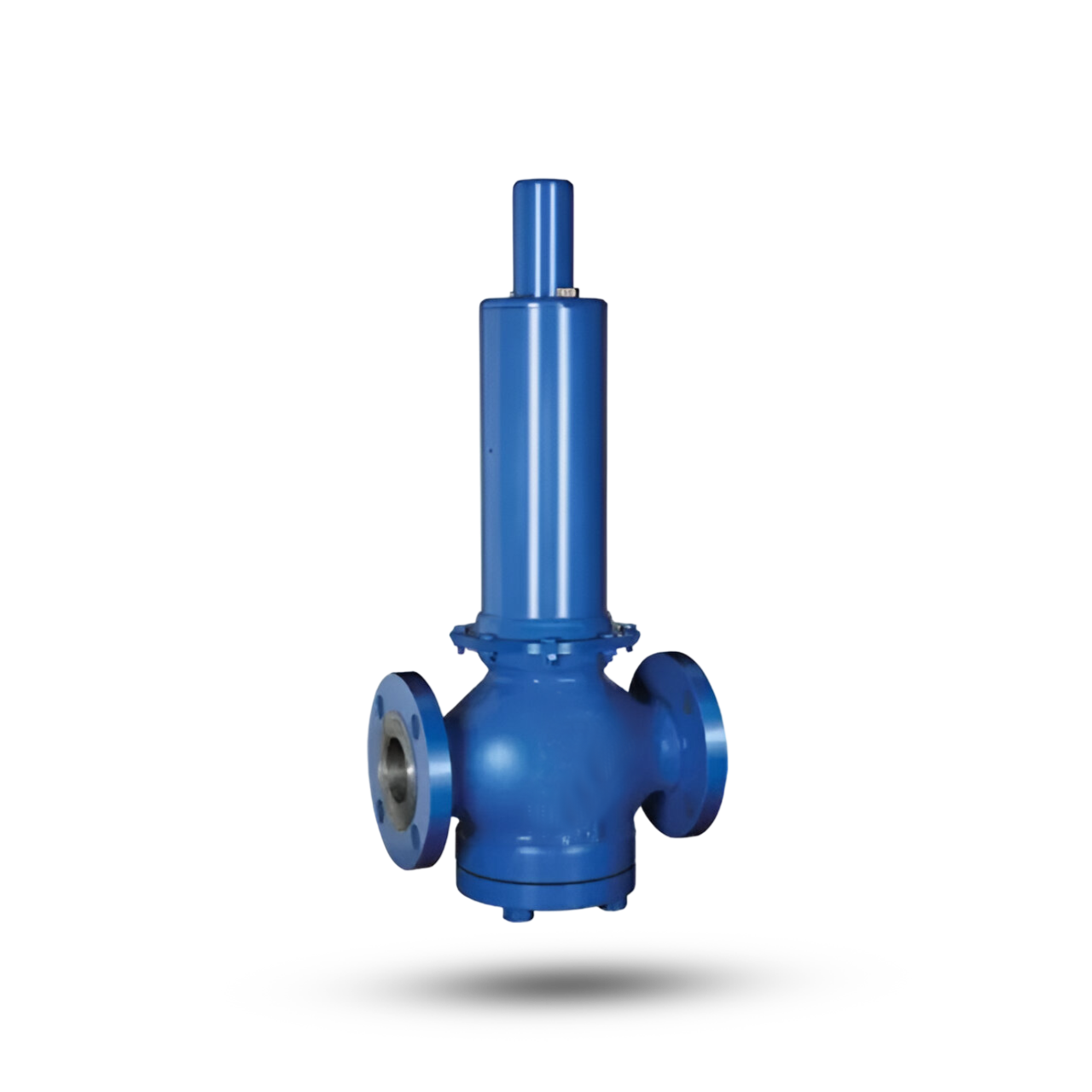
Downstream Pressure Regulating Valve is self contained, self Operated control device, which automatically reduce a higher inlet pressure to a steady lower downstream pressure regardless of changing flow rate and varying inlet pressure. It utilizes energy from the controlled system. The regulator operates on the simple principal of force balance. A Downward opening force is exerted by the actuator spring, which is balanced by the upward force exerted by the controlled outlet pressure acting below the diaphragm. Any drop in controlled outlet Pressure due to consumption of Fluid, disturbs the force balance and due to spring force diaphragm and stem move down pushing the valve plug away from seat. This results in the increased flow. The pressure reducing regulators are manufactured in a variety to manage downstream system pressures in low, medium, high flow application; model features a diaphragm/Piston type or combination of both to suit different applications. These regulators find applications throughout many industries including the Oil & Gas, Pulp & Paper, Power Generation and chemicals processing industries etc.
Specifications
Features
- Models are available for Steam, air, gas or liquid service with internal or external sensing.
- Reduces higher inlet Pressure to a constant lower outlet pressure.
- Moulded sensing diaphragm provide a good proportional band and registration of outlet pressure on the diaphragm allows excellent control sensitivity.
- Glandless Construction where positive zero gland leakage is required, the design scores over conventional solutions such as Bellow seal etc., as the gland itself is eliminated and hence there can’t be gland leakage. Glandless construction eliminates hystersis, resulting in improvement of sensitivity and repeatability of the valve.
- Outlet pressure is accurate over wide range of flow.
- Pilot-Operated main valve is not subjected to pressure fall off Characteristic of direct-acting PRV’s.
- Outlet pressure is adjustable over complete range of control spring.
- Operates automatically off line pressure.
- Heavy-duty, nylon-reinforced diaphragm.
- Round-shaped, soft seat seal provide drip-tight class VI closure.
- Diaphragm assembly guided top and bottom.
- Easily maintained without removal from the line.
- Pressure adjustment by single adjusting screw.
- Replaceable seat ring.
- Range of Body & Diaphragm material combinations to meet majority of requirements.
- IBR certification in From III C available.
- Designed ruggedly to withstand shocks.
- Simple and economic design.
Assurance
- Produced with Quality Systems accredited to ISO 9001 : 2008 by Bureau Veritas.
- Full material certification available for all major component Parts.
- Full guarantee on design and Performance.
- All testing performed to the requirements of ASME B16.34.
Desuperheater
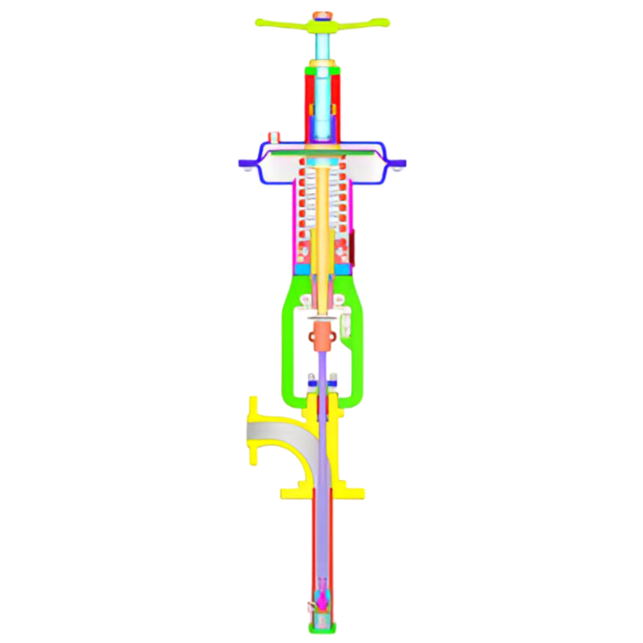
BUILT IN RELIABILITY PVCT-800 Desuperheater is a device that reduces the temperature of superheated steam so that it can be used effectively for heating or for other industrial use. This temperature reduction or attemperation is performed by desuperheater, which is essentially a device that injects a predetermined amount of water into a steam flow stream. The desuperheaters are highly effective in controlling steam temperature close to saturation point over a broad set of steam conditions The desuperheater provide effective heat transfer between steam and water. A highly effective desuperheater design and application ensures that costly problems are avoided including extended startup and shutdown times, reduced process efficiency and general wear of downstream piping and equipment. Pneucon incorporate latest technology in the spray nozzle design. The high quality surface finish minimises frictional losses, thereby ensuring that the total pressure difference between water and steam is available for atomisation of water.
Specifications
Features
- High efficient atomization.
- Accurate and repeatable control of fluid temperature.
- Tight shut off variable spray unit.
- High rangeability variable area spray unit.
- Erosion resistance materials of selection.
- Ease of installation.
- Low maintenance features.
- High integrity stem sealing arrangement.
- Thoroughly checked at factory to ensure that it meets the specified performance on site with high integrity.
- Quality assurance at every stage of manufacturing.
- Comprehensively designed and tested to ensure its optimum performance for the tough process Parameters specified.
- Built in latest technology in the spray nozzle designs.
Assurance
- Produced with Quality Systems accredited to ISO 9001 : 2008 by Bureau Veritas.
- Full material certification available for all major component Parts.
- Full guarantee on design and Performance.
- All testing performed to the requirements of ASME B16.34.
Power Cylinder
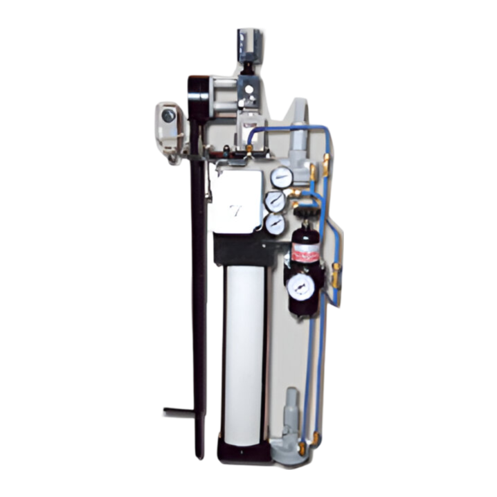
The PNEUCON Power Cylinders are widely used for accurately and positively positioning all types of plant regulators such as Dampers, ID and FD. fans in Boilers, Throttle Valves and Butterfly Valves. Power Cylinder can be arranged so that increase in control pressure moves the position either outwards or inwards
Specifications
Features
- Wide range available to meet most requirements.
- Reversal of piston direction in relation to the Control Signal easily achieved on site.
- Finish Cylinder barrel and piston rod.
- Low friction and long life.
Assurance
- Produced with Quality Systems accredited to ISO 9001 : 2008 by Bureau Veritas.
- Full material certification available for all major component Parts.
- Full guarantee on design and Performance.